Difference between revisions of "Importing RF Device Models"
Kazem Sabet (Talk | contribs) |
Kazem Sabet (Talk | contribs) |
||
| Line 34: | Line 34: | ||
{| class="wikitable" | {| class="wikitable" | ||
|- | |- | ||
| − | ! Device Type !! Symbol Name !! Schematic Symbol | + | ! Device Type !! Symbol Name !! Model Type !! Schematic Symbol |
|- | |- | ||
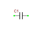
| − | | RF Capacitor || capacitor || [[File:G6a.png]] | + | | RF Capacitor || capacitor || one-port || [[File:G6a.png]] |
|- | |- | ||
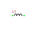
| − | | RF Inductor || inductor || [[File:G7a.png]] | + | | RF Inductor || inductor || one-port || [[File:G7a.png]] |
|- | |- | ||
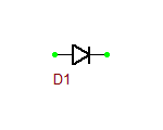
| − | | RF Diode || diode || [[File:G9.png]] | + | | RF Diode || diode || one-port || [[File:G9.png]] |
|- | |- | ||
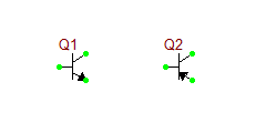
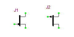
| − | | RF BJT || bjt_npn <br /> bjt_pnp || [[File:G11.png]] | + | | RF BJT || bjt_npn <br /> bjt_pnp || two-port || [[File:G11.png]] |
|- | |- | ||
| − | | RF JFET || jfet_n <br /> jfet_p || [[File:G12.png]] | + | | RF JFET || jfet_n <br /> jfet_p || two-port || [[File:G12.png]] |
|- | |- | ||
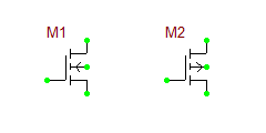
| − | | RF MOSFET || mosfet_n <br /> mosfet_p || [[File:G13a.png]] | + | | RF MOSFET || mosfet_n <br /> mosfet_p || two-port || [[File:G13a.png]] |
|- | |- | ||
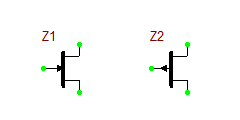
| − | | RF MESFET || mesfet_n <br /> mesfet_p || [[File:G14.png]] | + | | RF MESFET || mesfet_n <br /> mesfet_p || two-port || [[File:G14.png]] |
|- | |- | ||
| − | | One-Port|| one-port || [[File:G60.png]] | + | | One-Port|| one-port || one-port || [[File:G60.png]] |
|- | |- | ||
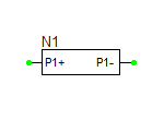
| − | | Two-Port|| two-port || [[File:G61.png]] | + | | Two-Port|| two-port || two-port || [[File:G61.png]] |
|- | |- | ||
| − | | Three-Port|| three-port || [[File:G62.png]] | + | | Three-Port|| three-port || three-port || [[File:G62.png]] |
|- | |- | ||
| − | | Four-Port|| four-port || [[File:G63.png]] | + | | Four-Port|| four-port || four-port || [[File:G63.png]] |
|- | |- | ||
| − | | Open End || open_end || [[File:G64.png]] | + | | Open End || open_end || one-port || [[File:G64.png]] |
|- | |- | ||
| − | | Bend || bend_junction || [[File:G65.png]] | + | | Bend || bend_junction || two-port || [[File:G65.png]] |
|- | |- | ||
| − | | Step Junction || step_junction || [[File:G66.png]] | + | | Step Junction || step_junction || two-port || [[File:G66.png]] |
|- | |- | ||
| − | | Tee Junction || tee_junction || [[File:G67.png]] | + | | Tee Junction || tee_junction || three-port || [[File:G67.png]] |
|- | |- | ||
| − | | Cross Junction || cross_junction || [[File:G68.png]] | + | | Cross Junction || cross_junction || four-port || [[File:G68.png]] |
|- | |- | ||
|} | |} | ||
Revision as of 13:35, 14 August 2014
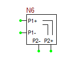
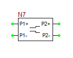
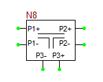
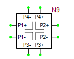
Multiport Network device, i.e. one-ports, two-ports, three-ports and four-ports, are all modeled based on their frequency-domain S-parameters. Most active and passive RF devices can be modeled as multipart networks. For example, RF diodes can be modeled as one-ports, while RF transistors (BJTs, JFETs, MOSFETs, and MESFETs) can be modeled as two-ports. Many semiconductor manufacturers publish S-parameter data sets for their RF devices. The manufacturer data sheets usually contain S-parameters in Mag/Phase format tabulated as a function of frequency expressed in GHz. On the other hand, you can model many passive devices such as filters, directional couplers, hybrids, etc. as multiport structures using full-wave electromagnetic simulators like EM.Cube. The port characteristics of such devices are typically written into data files as a function of frequency. A particular case of interest is transmission line components with complex geometries or material composition, for which RF.Spice does not provide any database models. as an example, consider the case of a "Finline" transmission line. In a finlike-based circuit, you may need one of more of the following general transmission line components:
- Open End
- Bend (right-angled or mitered)
- Step Junction
- Tee Junction (symmetric or asymmetric, possibly with a notch)
- Cross Junction (symmetric or asymmetric)
RF. Spice currently does not provide any models for finline components. However, you can use EM.Cube to analyze various finline structures over a frequency range of interest and generate S-parameter data sets for them.
RF.Spice allows you to import S-parameter-based models of RF devices from text files. Before describing how to import S-parameter data files, let us first discuss the format of the data files in more details. S-parameter data files must have a ".TXT" file extension. These files must start with a ".model" and a ".symbol" statement:
.model <model_name>
.symbol <symbol_name>
Example:
.model MyNewRFBJT
.symbol bjt_npn
The model statement specifies the name of your RF device model. The symbol statement determines its device type and schematic symbol. The symbol_name can only be one of the following list:
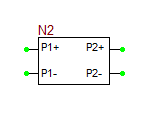
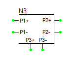
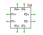
The model text file can have any number of comment lines at the beginning of the file. Comment lines are preceded by "*" or "!". All the text after these characters will be ignored.
